Key points
- Capacitance C = Q/V, measured in farads (F).
- Parallel: same p.d., charges add, so C = C₁ + C₂.
- Series: same charge, p.d.s add, so 1/C = 1/C₁ + 1/C₂.
- Energy stored W = ½QV = ½CV² = ½Q²/C, the area under the V-Q graph.
- Parallel plate capacitor: C = εA/d, where ε = εᵣε₀.
- Charge sharing between capacitors loses energy as thermal energy in the wires.
Capacitance and how capacitors combine
Capacitors in series and parallel combine according to two rules. In parallel the capacitances add: C = C₁ + C₂. In series the reciprocals add: 1/C = 1/C₁ + 1/C₂. Both come from the definition of capacitance, C = Q/V, and the energy stored in a capacitor is W = ½QV = ½CV².
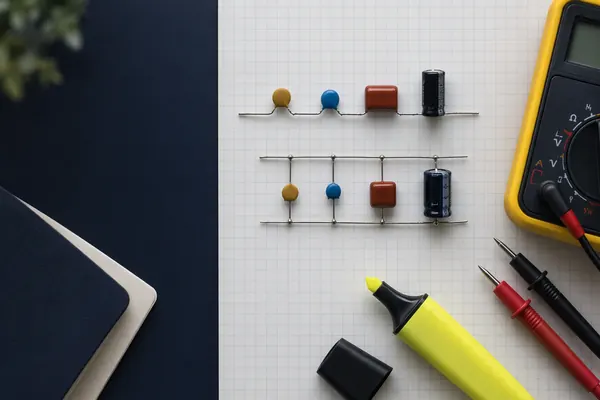
A capacitor is two conducting plates separated by an insulator. Connect it to a supply and charge flows on to one plate and off the other, leaving +Q on one plate and −Q on the other. The capacitor as a whole stays neutral. When we say 'the charge on a capacitor' we mean the magnitude of the charge on one plate.
Capacitance is the charge stored per unit p.d. across the capacitor. The unit is the farad (F), where 1 F = 1 C V⁻¹. A farad is huge, so real capacitors are measured in μF, nF and pF.
This guide sits in the Capacitors topic of module 6. Once you have the combining rules and the energy equation, go on to capacitor discharge, which adds the time dimension.
Key equations and units
C = Q / V
- C = capacitance (F)
- Q = charge on one plate (C)
- V = p.d. across the capacitor (V)
Rearranged, Q = CV, which says the charge stored is proportional to the p.d. A graph of Q against V is a straight line through the origin with gradient C.
W = ½QV = ½CV² = ½Q²/C
- W = energy stored (J)
- Q = charge (C)
- V = p.d. (V)
- C = capacitance (F)
The three forms are the same equation after substituting Q = CV. Choose the form that uses the quantities you are given.
C = ε₀A/d (with a dielectric: C = εA/d, ε = εᵣε₀)
- ε₀ = permittivity of free space, 8.85 × 10⁻¹² F m⁻¹
- ε = permittivity of the dielectric (F m⁻¹)
- εᵣ = relative permittivity of the dielectric (no unit)
- A = overlap area of the plates (m²)
- d = plate separation (m)
This is for a parallel plate capacitor. Air is close enough to a vacuum that you can use ε₀ for air.
| Prefix | Symbol | Factor | Example |
|---|---|---|---|
| micro | μ | 10⁻⁶ | 470 μF = 4.7 × 10⁻⁴ F |
| nano | n | 10⁻⁹ | 100 nF = 1.0 × 10⁻⁷ F |
| pico | p | 10⁻¹² | 220 pF = 2.2 × 10⁻¹⁰ F |
Capacitors in parallel
Parallel capacitors are connected side by side, so each one has the same p.d. across it. The supply must provide the charge for all of them, so the total charge is the sum of the charges on each.
Derivation. Let the p.d. be V. Then Q₁ = C₁V and Q₂ = C₂V. The total charge is Q = Q₁ + Q₂ = C₁V + C₂V = (C₁ + C₂)V. The combined capacitance is C = Q/V, so:
C = C₁ + C₂ + C₃ + …
- C = total capacitance of the parallel combination (F)
Adding a capacitor in parallel is like making the plate area bigger, so the total always increases.
The total capacitance is larger than any single capacitor. Each capacitor stores a charge in proportion to its own capacitance, so the biggest capacitor stores the most charge.
Capacitors in series
In series, the capacitors are connected end to end. The same current flows through each, so the same charge Q is stored on each capacitor (the plates between two capacitors are isolated, so any charge on one must equal the opposite charge on the next). The supply p.d. is shared between them.
Derivation. The p.d. across each capacitor is V₁ = Q/C₁ and V₂ = Q/C₂. The supply p.d. is V = V₁ + V₂ = Q/C₁ + Q/C₂. The combined capacitance is C = Q/V, so V = Q/C. Divide through by Q:
1/C = 1/C₁ + 1/C₂ + 1/C₃ + …
- C = total capacitance of the series combination (F)
For two capacitors only, this is the same as C = C₁C₂ / (C₁ + C₂).
The total capacitance is smaller than the smallest capacitor in the chain. In series, the p.d. across each capacitor is inversely proportional to its capacitance: V₁ : V₂ = C₂ : C₁. The smaller capacitor gets the larger share of the p.d.
Energy stored in a capacitor
Charging a capacitor means doing work to push charge on to the plates against the p.d. that is already there. That work is stored as electric potential energy in the capacitor.
Derivation. When the p.d. is V, moving a small extra charge ΔQ on to the capacitor needs work ΔW = VΔQ. This is the area of a thin strip on a graph of V against Q. As the capacitor charges, V rises, because V = Q/C. The total work is the sum of all the strips, which is the area under the V-Q graph. The graph is a straight line through the origin, so the area is a triangle:
W = ½QV
- Area of triangle = ½ × base × height = ½ × Q × V
Substitute Q = CV to get W = ½CV², or V = Q/C to get W = ½Q²/C.
Be careful with the factor of ½. The energy supplied by a battery moving charge Q through p.d. V is QV, but only half of that ends up in the capacitor. The rest is transferred as thermal energy in the resistance of the circuit, however small that resistance is.
Energy also tells you how a capacitor behaves as a power source. It releases its energy quickly because the charge can flow out fast, which is why capacitors are used in camera flashes and defibrillators. Compared with a battery they store far less energy for their size, but they can deliver it much faster.
Parallel plate capacitors and permittivity
The capacitance of a parallel plate capacitor depends on its geometry and on the material between the plates. For plates of overlap area A separated by distance d, with air or vacuum between them:
C = ε₀A / d
- ε₀ = 8.85 × 10⁻¹² F m⁻¹
C is proportional to A and inversely proportional to d. Doubling the plate area doubles the capacitance. Doubling the gap halves it.
If an insulating material, called a dielectric, fills the gap, the capacitance increases. The material has a permittivity ε that is larger than ε₀. We write ε = εᵣε₀, where εᵣ is the relative permittivity (a number with no unit, always greater than 1 for a dielectric). Then C = εA/d = εᵣε₀A/d.
Why does a dielectric help? The molecules in the dielectric are polarised by the field between the plates, with their positive ends pulled slightly towards the negative plate and vice versa. This creates a small field of its own that opposes the field of the plates. The net field is weaker, so for the same charge on the plates the p.d. is smaller. Since C = Q/V, a smaller V for the same Q means a larger C. A dielectric also stops the plates touching and lets you use a closer spacing.
Worked examples
Two capacitors in series
A 4.7 μF capacitor and a 10 μF capacitor are connected in series across a 12 V supply. Calculate (a) the total capacitance, (b) the charge on each capacitor, (c) the p.d. across each capacitor, and (d) the total energy stored.
- (a) 1/C = 1/4.7 + 1/10 = 0.2128 + 0.1000 = 0.3128 μF⁻¹, so C = 3.197 μF.
- (b) The charge is the same on each: Q = CV = 3.197 × 10⁻⁶ × 12 = 3.84 × 10⁻⁵ C.
- (c) V₁ = Q/C₁ = 3.84 × 10⁻⁵ / 4.7 × 10⁻⁶ = 8.16 V. V₂ = Q/C₂ = 3.84 × 10⁻⁵ / 10 × 10⁻⁶ = 3.84 V. Check: 8.16 + 3.84 = 12.0 V.
- (d) W = ½CV² = ½ × 3.197 × 10⁻⁶ × 12² = 2.30 × 10⁻⁴ J.
Answer (a) 3.2 μF. (b) 38 μC on each. (c) 8.2 V across the 4.7 μF and 3.8 V across the 10 μF. (d) 0.23 mJ.
A combined network
A 6.0 μF capacitor is connected in parallel with a combination of a 3.0 μF capacitor in series with a 6.0 μF capacitor. The network is connected to a 9.0 V supply. Calculate (a) the total capacitance, (b) the total charge, and (c) the p.d. across the 3.0 μF capacitor.
- (a) The series pair: 1/C = 1/3.0 + 1/6.0 = 0.5, so C = 2.0 μF.
- This 2.0 μF branch is in parallel with the 6.0 μF, so C = 2.0 + 6.0 = 8.0 μF.
- (b) Q = CV = 8.0 × 10⁻⁶ × 9.0 = 7.2 × 10⁻⁵ C.
- (c) The charge on the series branch = 2.0 × 10⁻⁶ × 9.0 = 1.8 × 10⁻⁵ C, and this is the charge on each capacitor in that branch.
- V = Q/C = 1.8 × 10⁻⁵ / 3.0 × 10⁻⁶ = 6.0 V.
Answer (a) 8.0 μF. (b) 72 μC. (c) 6.0 V (the other 3.0 V is across the 6.0 μF in that branch).
Sharing charge and losing energy
A 100 μF capacitor is charged to 12 V and disconnected from the supply. It is then connected in parallel with an uncharged 50 μF capacitor. Calculate (a) the final p.d., (b) the energy stored before and after, and (c) explain the difference.
- (a) The initial charge is Q = CV = 100 × 10⁻⁶ × 12 = 1.2 × 10⁻³ C. Charge is conserved.
- The total capacitance is 100 + 50 = 150 μF, so V = Q/C = 1.2 × 10⁻³ / 150 × 10⁻⁶ = 8.0 V.
- (b) Before: W = ½ × 100 × 10⁻⁶ × 12² = 7.2 × 10⁻³ J.
- After: W = ½ × 150 × 10⁻⁶ × 8.0² = 4.8 × 10⁻³ J.
- (c) The energy decreases by 2.4 × 10⁻³ J. Charge flows through the connecting wires, which have resistance, so energy is transferred as thermal energy (and some radiated).
Answer (a) 8.0 V. (b) 7.2 mJ before and 4.8 mJ after. (c) 2.4 mJ is dissipated as thermal energy in the wires as charge flows between the capacitors.
A parallel plate capacitor with a dielectric
A parallel plate capacitor has square plates of side 0.141 m separated by an air gap of 0.50 mm, so the plate area is 0.020 m². Calculate (a) its capacitance. A sheet of dielectric of relative permittivity 3.0 then fills the gap. Calculate (b) the new capacitance, and (c) the energy stored at 50 V in each case.
- (a) C = ε₀A/d = 8.85 × 10⁻¹² × 0.020 / 0.50 × 10⁻³ = 3.54 × 10⁻¹⁰ F.
- (b) With the dielectric, C = εᵣε₀A/d = 3.0 × 3.54 × 10⁻¹⁰ = 1.06 × 10⁻⁹ F.
- (c) Air: W = ½CV² = ½ × 3.54 × 10⁻¹⁰ × 50² = 4.4 × 10⁻⁷ J.
- Dielectric: W = ½ × 1.06 × 10⁻⁹ × 50² = 1.3 × 10⁻⁶ J.
Answer (a) 354 pF. (b) 1.06 nF. (c) 0.44 μJ with air and 1.3 μJ with the dielectric, at the same 50 V.
Common mistakes
- Using the series rule for parallel, or the other way round. Parallel capacitors simply add. It is resistors in series that simply add, which is the reverse of the pattern for capacitors.
- Forgetting to flip 1/C. After adding the reciprocals you still need to invert. If your answer for two capacitors in series is larger than either capacitor, you have not flipped.
- Using the supply p.d. in the energy equation for one capacitor. In series, each capacitor has only part of the supply p.d. Use the p.d. across that capacitor.
- Dropping the ½ in W = ½QV. The area under the V-Q graph is a triangle, not a rectangle.
- Mixing up the gradient of the V-Q and Q-V graphs. On a Q-V graph, the gradient is C. On a V-Q graph, the gradient is 1/C.
- Missing prefixes. 4.7 μF is 4.7 × 10⁻⁶ F, not 4.7 × 10⁻³ F.
- Saying the charge is shared equally in series. The charge is the same on each, but the p.d.s are generally different.
How OCR A examines this topic
Capacitors are assessed in Module 6, so expect them in the papers covering that content and in the synoptic paper. Check your copy of the specification for exact paper coverage. Typical questions ask you to combine capacitors, find the charge and p.d. on each in a network, calculate the energy stored, and explain or sketch graphs of V against Q.
Look for the 'show that' and 'explain' command words. An explanation of why the series capacitors store the same charge needs the idea that the charge on the isolated plates between the capacitors must be equal and opposite. An explanation of why a dielectric increases capacitance needs polarisation, a weaker field, and a smaller p.d. for the same charge.
Synoptic links. The energy and charge ideas link to capacitor discharge, where the same capacitor loses charge exponentially. The idea of the field between plates connects to Coulomb's law and electric fields, where E = V/d for the uniform field between charged plates. The combination rules also mirror those for resistors in resistance and resistivity, with series and parallel swapped.
Practice questions
Three 12 μF capacitors are available. Calculate the total capacitance when they are connected (a) all in series, and (b) all in parallel.3 marks
Show the answer
Answer: (a) 4.0 μF. (b) 36 μF.
(a) 1/C = 3/12, so C = 4.0 μF. (b) C = 12 + 12 + 12 = 36 μF.
Calculate the total capacitance of a 2.2 μF, a 3.3 μF and a 4.7 μF capacitor connected in series.3 marks
Show the answer
Answer: 1.0 μF (1.03 μF).
1/C = 1/2.2 + 1/3.3 + 1/4.7 = 0.4545 + 0.3030 + 0.2128 = 0.9703 μF⁻¹, so C = 1.03 μF.
A 1500 μF capacitor is charged to 9.0 V. Calculate the charge on it and the energy stored.3 marks
Show the answer
Answer: Q = 0.0135 C and W = 0.061 J.
Q = CV = 1500 × 10⁻⁶ × 9.0 = 0.0135 C. W = ½CV² = ½ × 1500 × 10⁻⁶ × 81 = 0.06075 J.
A 470 μF capacitor stores 0.15 J. Calculate the p.d. across it.3 marks
Show the answer
Answer: 25 V.
W = ½CV², so V = √(2W/C) = √(2 × 0.15 / 470 × 10⁻⁶) = √638.3 = 25.3 V.
A 20 μF and a 30 μF capacitor are connected in series across a 10 V supply. Calculate the p.d. across each capacitor and the total energy stored.5 marks
Show the answer
Answer: 6.0 V across the 20 μF, 4.0 V across the 30 μF, and 600 μJ in total.
C = (20 × 30)/(20 + 30) = 12 μF. Q = 12 × 10⁻⁶ × 10 = 1.2 × 10⁻⁴ C. V₁ = 120/20 = 6.0 V. V₂ = 120/30 = 4.0 V. W = ½ × 12 × 10⁻⁶ × 10² = 6.0 × 10⁻⁴ J.
An air-filled parallel plate capacitor has a capacitance of 220 pF and a plate separation of 0.10 mm. Calculate the plate area.3 marks
Show the answer
Answer: 2.5 × 10⁻³ m².
C = ε₀A/d, so A = Cd/ε₀ = 220 × 10⁻¹² × 0.10 × 10⁻³ / 8.85 × 10⁻¹² = 2.49 × 10⁻³ m².
Next steps
Now that you can combine capacitors and calculate energy, learn how they charge and discharge over time in capacitor discharge. The field between the plates is covered in Coulomb's law and electric fields. Browse everything in module 6, or practise this topic with step-by-step marking. It is free to start.
Frequently asked questions
How do you add capacitors in series and parallel?
In parallel, add the capacitances: C = C₁ + C₂. In series, add the reciprocals: 1/C = 1/C₁ + 1/C₂, then invert. This is the opposite pattern to resistors.
Why is the total capacitance smaller in series?
In series, the same charge sits on each capacitor but the supply p.d. is shared between them. Since C = Q/V, the same Q with a larger total p.d. gives a smaller combined capacitance. It is always less than the smallest capacitor in the chain.
Why is there a ½ in the energy stored in a capacitor?
The p.d. rises from zero to V as the capacitor charges, so the average p.d. is V/2. The work done is the area under the V-Q graph, a triangle with area ½QV. The other half of the energy from the supply is transferred as thermal energy in the circuit.
What does a dielectric do in a capacitor?
A dielectric is an insulator between the plates that is polarised by the field. It weakens the field, so for the same charge the p.d. is smaller, and the capacitance C = Q/V is larger. The capacitance becomes C = εᵣε₀A/d.
What is the unit of capacitance?
The farad (F), which is one coulomb per volt. In practice capacitors are measured in microfarads (μF), nanofarads (nF) and picofarads (pF).
Related guides
Written for the OCR A Level Physics A (H556) specification. Questions are original and written in exam style; they are not taken from OCR papers. Spotted a mistake? Tell us.