Key points
- Vout = R₂ / (R₁ + R₂) × Vin, with Vout measured across R₂ and assuming no current is drawn by whatever is connected to the output.
- The larger resistor gets the larger share of the supply p.d., because the same current flows through both.
- Put the sensor so the output moves the way you need: NTC thermistor on top and fixed resistor below gives an output that rises as it gets hotter.
- A potentiometer is a potential divider with a sliding contact, so Vout can be varied from 0 V to Vin.
- Connecting a load across the output lowers Vout, because the load is in parallel with R₂.
What a potential divider does
Potential divider circuits let you take a fraction of a supply voltage. Two resistors are connected in series across the supply, and the output is taken from across one of them. Because the same current passes through both resistors, the p.d. across each is proportional to its resistance, so the bigger resistor takes the bigger share.
They are everywhere in electronics: a volume control, a light-sensitive night light, a temperature alarm. If you can use the potential divider equation, spot which resistor the output is across, and say what happens when a resistance changes, you can answer almost any question on this topic.
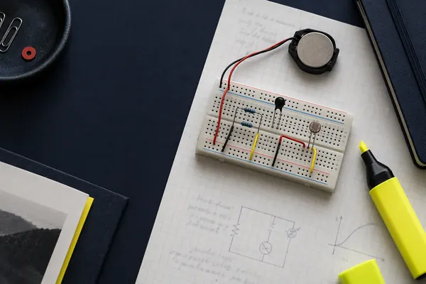
This topic builds on resistance and resistivity, and it leads into emf and internal resistance, where a real cell is treated as an ideal source with a resistor in series. The full list of topics is on the Module 4 hub.
The potential divider equation
The equation comes straight from V = IR. With no current taken from the output, the current through both resistors is I = Vin / (R₁ + R₂), because the total resistance in series is R₁ + R₂. The output is the p.d. across R₂, which is Vout = IR₂.
Vout = R₂ / (R₁ + R₂) × Vin
- Vout = p.d. across R₂ (V)
- Vin = supply p.d. across both resistors (V)
- R₁, R₂ = resistances of the two resistors (Ω)
You can also write Vout / Vin = R₂ / (R₁ + R₂). Any unit of resistance works as long as you use the same one for both.
There is a quick check you can do on every answer. If R₁ = R₂ the output is exactly half of Vin. If R₂ is much larger than R₁, Vout is close to Vin. If R₂ is much smaller, Vout is close to 0 V. Vout can never be bigger than Vin.
A second, equivalent statement is that the p.d.s are in the same ratio as the resistances: V₁ / V₂ = R₁ / R₂. This is sometimes quicker when the question asks for the p.d. across both resistors.
Series and parallel resistors, and Kirchhoff's laws
Many circuits need you to combine resistors before you can find a current or p.d. The rules follow from conservation of charge and energy.
| Arrangement | Total resistance | What is the same | What is shared |
|---|---|---|---|
| Series | R = R₁ + R₂ + R₃ | Current | Supply p.d. (larger R gets larger p.d.) |
| Parallel | 1/R = 1/R₁ + 1/R₂ + 1/R₃ | p.d. | Supply current (smaller R carries larger current) |
Kirchhoff's first law says the total current into a junction equals the total current out of it. This is conservation of charge. Kirchhoff's second law says that around any closed loop, the sum of the emfs equals the sum of the p.d.s across components. This is conservation of energy.
Together with V = IR these laws explain the divider. The series loop gives Vin = V₁ + V₂, and the first law gives the same current through both resistors. For two resistors in parallel, a handy shortcut is R = R₁R₂ / (R₁ + R₂), which is the product over the sum. The total parallel resistance is always less than the smallest resistor.
Sensor circuits with thermistors and LDRs
A thermistor or LDR is a resistor whose value changes with the environment. As covered in resistance and resistivity, an NTC thermistor's resistance falls as it gets hotter and an LDR's resistance falls as light intensity rises. Putting one of them in a potential divider converts that change in resistance into a change in output voltage.
Which way the output changes depends on where the sensor is. The sensor's share of the supply p.d. is large when its resistance is large.
- NTC thermistor as R₁ (top), fixed resistor as R₂ (bottom): heating lowers R₁, so R₂ takes a bigger share and Vout rises.
- NTC thermistor as R₂ (bottom), fixed resistor as R₁ (top): heating lowers R₂, so its share falls and Vout falls.
- LDR as R₁ (top): more light lowers R₁ and Vout rises. LDR as R₂ (bottom): more light lowers R₂ and Vout falls.
The curve is not a straight line because the thermistor's resistance does not change linearly with temperature. That matters in an exam: do not describe the output as "proportional" to temperature.
A typical use is a switch. The output is connected to a transistor or comparator circuit that turns something on when Vout passes a set value. To change the temperature at which this happens, you change the fixed resistor. A larger fixed resistor gives a larger Vout at the same thermistor resistance, so the threshold is reached at a lower temperature.
Potentiometers and variable outputs
A potentiometer is a resistor track with a sliding contact. The full supply is connected across the ends of the track, and the output is taken between the slider and one end. Moving the slider changes R₁ and R₂ while R₁ + R₂ stays fixed, so Vout can be adjusted smoothly from 0 V to Vin.
For a uniform track, the resistance of each part is proportional to its length. If the slider is a distance x from the 0 V end of a track of length L, then Vout = (x / L) × Vin. A 12 V supply across a 1.00 m wire with the slider 0.30 m from the bottom gives 3.6 V.
This is also how you control a circuit from zero volts upwards when investigating I-V characteristics. A variable resistor in series can only reduce the current, whereas a potential divider arrangement lets the p.d. across a component start at zero.
The loading effect
The equation assumes nothing draws current from the output. If you connect a load, such as a lamp, a motor or a low-resistance voltmeter, across R₂, the load is in parallel with R₂. The combined resistance is lower than R₂, so the output p.d. falls.
The fix is to make the load resistance much larger than R₂. Then the parallel combination is only slightly less than R₂ and Vout hardly changes. A voltmeter should have a very high resistance for the same reason, so it does not disturb the circuit it is measuring.
Worked examples
Basic divider
A 12 V supply is connected across a 4.7 kΩ resistor in series with a 3.3 kΩ resistor. Calculate the p.d. across the 3.3 kΩ resistor.
- Total resistance = 4.7 + 3.3 = 8.0 kΩ.
- Vout = R₂ / (R₁ + R₂) × Vin = 3.3 / 8.0 × 12.
- Vout = 0.4125 × 12 = 4.95 V.
Answer 4.95 V, so 5.0 V to 2 significant figures.
Temperature sensor
An NTC thermistor is in series with a fixed 2.2 kΩ resistor across a 9.0 V supply. The output is taken across the fixed resistor. The thermistor has a resistance of 5.0 kΩ at 20 °C and 0.80 kΩ at 60 °C. Calculate Vout at each temperature and state how the output changes as the temperature rises.
- At 20 °C: Vout = 2.2 / (5.0 + 2.2) × 9.0 = 2.2 / 7.2 × 9.0 = 2.75 V.
- At 60 °C: Vout = 2.2 / (0.80 + 2.2) × 9.0 = 2.2 / 3.0 × 9.0 = 6.6 V.
- As temperature rises, the thermistor resistance falls, so the fixed resistor takes a larger share of the supply p.d. and Vout increases.
Answer 2.8 V at 20 °C and 6.6 V at 60 °C. The output increases as the temperature rises.
Loading effect
A 6.0 V supply is connected across two 10 kΩ resistors in series. (a) State the output p.d. across the lower resistor with nothing connected to the output. (b) A 10 kΩ load is now connected across the lower resistor. Calculate the new output p.d.
- (a) The resistors are equal, so Vout = 6.0 / 2 = 3.0 V.
- (b) The 10 kΩ load is in parallel with the lower 10 kΩ resistor: R = (10 × 10) / (10 + 10) = 5.0 kΩ.
- The circuit is now 10 kΩ in series with 5.0 kΩ: Vout = 5.0 / (10 + 5.0) × 6.0 = 2.0 V.
Answer (a) 3.0 V; (b) 2.0 V. The load lowers the output because the lower resistance takes a smaller share of the supply p.d.
Choosing a resistor
A potential divider is to give an output of 2.5 V from a 10 V supply. The lower resistor R₂ is 1.0 kΩ. Calculate the value of the upper resistor R₁.
- Vout / Vin = R₂ / (R₁ + R₂), so 2.5 / 10 = 1.0 / (R₁ + 1.0).
- R₁ + 1.0 = 1.0 × 10 / 2.5 = 4.0 kΩ.
- R₁ = 4.0 − 1.0 = 3.0 kΩ.
Answer R₁ = 3.0 kΩ. Check: 1.0 / 4.0 × 10 = 2.5 V.
Common mistakes
- Saying the sensor circuit "increases the voltage". A divider can only give a fraction of Vin, never more.
- Adding resistances in parallel instead of using 1/R = 1/R₁ + 1/R₂.
- Describing the output of a thermistor divider as "proportional to temperature".
- Mixing up which way the output moves when the sensor swaps from the top to the bottom position.
- Giving kΩ answers in ohms or vice versa in the same equation. Use the same unit for R₁ and R₂.
- Saying that current is "used up" by a resistor. The current is the same all the way round a series circuit.
How OCR A examines potential dividers
Potential dividers appear in short calculations and in longer questions with a sensor. A frequent pattern is to give you a table or graph of thermistor or LDR resistance against temperature or light level, ask you to read a resistance value, then use it in the potential divider equation to find Vout.
- Calculation: Vout from given resistances, or the resistance needed for a given output.
- Explanation: how and why Vout changes when a thermistor is heated or an LDR is lit, in terms of the changing share of p.d.
- Design: which component should go where for a switch that operates when it gets dark or hot, and how to change the switching point.
- Synoptic links: resistivity and temperature dependence, internal resistance, and in Module 6 the charging and discharging of capacitors through resistors.
Practice questions
A 6.0 V battery is connected across a 100 Ω resistor in series with a 200 Ω resistor. Calculate the p.d. across the 200 Ω resistor.2 marks
Show the answer
Answer: 4.0 V
Vout = 200 / (100 + 200) × 6.0 = 0.667 × 6.0 = 4.0 V.
A 6.0 Ω and a 3.0 Ω resistor are in parallel, and this pair is in series with a 4.0 Ω resistor across a 12 V supply. Calculate (a) the total resistance, (b) the supply current, (c) the current in the 3.0 Ω resistor.4 marks
Show the answer
Answer: (a) 6.0 Ω; (b) 2.0 A; (c) 1.3 A
(a) Parallel pair: 1/R = 1/6.0 + 1/3.0 = 0.5, so R = 2.0 Ω. Total = 2.0 + 4.0 = 6.0 Ω. (b) I = 12 / 6.0 = 2.0 A. (c) p.d. across the pair = 2.0 × 2.0 = 4.0 V, so the current in the 3.0 Ω resistor = 4.0 / 3.0 = 1.33 A.
An LDR is the upper component and a 10 kΩ resistor is the lower component, across a 5.0 V supply. The LDR has a resistance of 1.0 kΩ in bright light and 80 kΩ in the dark. The output is across the 10 kΩ resistor. Calculate Vout in each case.3 marks
Show the answer
Answer: 4.5 V in bright light and 0.56 V in the dark
Bright: Vout = 10 / (1.0 + 10) × 5.0 = 4.545 V. Dark: Vout = 10 / (80 + 10) × 5.0 = 0.556 V.
A potentiometer consists of a uniform wire 1.00 m long connected across a 12 V supply. The slider is 0.30 m from the 0 V end. Calculate the output p.d.2 marks
Show the answer
Answer: 3.6 V
Vout = (0.30 / 1.00) × 12 = 3.6 V.
Two 1.0 kΩ resistors in series across 12 V give an output of 6.0 V. A 1.0 kΩ load is connected across the lower resistor. Calculate the new output p.d. and explain the change.3 marks
Show the answer
Answer: 4.0 V
The load and lower resistor in parallel: 1.0 × 1.0 / 2.0 = 0.50 kΩ. Vout = 0.50 / (1.0 + 0.50) × 12 = 4.0 V. The parallel resistance is lower than 1.0 kΩ, so it takes a smaller share of the supply p.d.
A student measures the output of a divider made from two 100 kΩ resistors across 10 V using a voltmeter of resistance 10 kΩ across the lower resistor. Calculate the reading and explain why it differs from 5.0 V.3 marks
Show the answer
Answer: 0.83 V. The voltmeter is in parallel with the lower resistor and has a much lower resistance, so it greatly reduces the resistance of that part of the circuit.
Parallel resistance: 100 × 10 / 110 = 9.09 kΩ. Vout = 9.09 / (100 + 9.09) × 10 = 0.833 V.
Next steps
Next, see how a real battery behaves like a divider with its own internal resistance in emf and internal resistance. If you want to revisit why a thermistor or LDR's resistance changes, go back to resistance and resistivity. When you are ready to test yourself, practise this topic with step-by-step marking, free to start.
Frequently asked questions
What is the potential divider equation?
Vout = R₂ / (R₁ + R₂) × Vin, where Vout is the p.d. across R₂ and Vin is the supply p.d. across both resistors. It assumes that no current is drawn from the output.
How does a thermistor potential divider work?
The thermistor's resistance changes with temperature, so its share of the supply p.d. changes. With an NTC thermistor above a fixed resistor and the output across the fixed resistor, Vout rises as the temperature rises. Swap their positions and Vout falls.
Why does connecting a load reduce the output of a potential divider?
The load is in parallel with the resistor the output is taken across, so the combined resistance is lower than that resistor alone. A lower resistance takes a smaller share of the supply p.d., so Vout falls.
What is the difference between a potentiometer and a variable resistor?
A potentiometer uses all three terminals as a potential divider, so the output p.d. can vary from 0 V to the full supply. A variable resistor uses two terminals to vary the resistance and can only limit the current.
Can the output of a potential divider be higher than the input?
No. The output is the p.d. across only part of the series circuit, so it is always a fraction of the supply p.d. A larger output would need an amplifier or a different supply.
Related guides

Written for the OCR A Level Physics A (H556) specification. Questions are original and written in exam style; they are not taken from OCR papers. Spotted a mistake? Tell us.