Key points
- Flux Φ = BA cos θ, with θ measured from the normal to the coil. Flux linkage = NΦ.
- Faraday's law: ε = −Δ(NΦ)/Δt, the gradient of the flux linkage against time graph.
- Lenz's law: the induced effect opposes the change, which is conservation of energy in action.
- Moving rod: ε = BLv, with the rod, field and motion mutually at right angles.
- Rotating coil: peak emf NBAω, greatest when the flux linkage is passing through zero.
- Transformer: Vs/Vp = Ns/Np, and efficiency = IsVs/IpVp × 100%.
Electromagnetic induction in plain terms
Faraday's law and Lenz's law describe how a changing magnetic field produces an emf. Faraday's law says the induced emf equals the rate of change of flux linkage: ε = −Δ(NΦ)/Δt. Lenz's law explains the minus sign: the induced emf always acts to oppose the change that causes it.
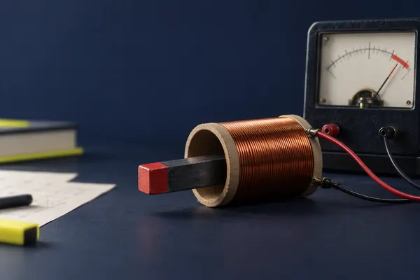
Electromagnetic induction is how nearly all electricity is generated. When the magnetic field through a circuit changes, an emf is induced in it. If the circuit is complete, a current flows. You can change the field through a coil by moving a magnet, by moving the coil, by turning the coil, or by changing the current in a nearby coil.
This guide builds on magnetic fields and flux density, so make sure you know what the tesla measures. It sits in the Electromagnetism topic of module 6.
Magnetic flux and flux linkage
Magnetic flux Φ measures how much magnetic field passes through an area. For a uniform field B passing through a flat area A, with the angle θ measured between the field and the normal (the line at right angles to the area):
Φ = BA cos θ
- Φ = magnetic flux (Wb, where 1 Wb = 1 T m²)
- B = magnetic flux density (T)
- A = area of the coil (m²)
- θ = angle between the field and the normal to the coil
Flux is greatest when the field is at right angles to the plane of the coil (θ = 0), and zero when the field is along the plane of the coil (θ = 90°).
A coil with N turns has the same flux through each turn, so the flux linkage is the flux multiplied by the number of turns:
flux linkage = NΦ = NBA cos θ
- N = number of turns on the coil
- NΦ = flux linkage (Wb turns)
Treat the unit as the weber (Wb) or weber turn. Both are acceptable in A-level answers.
Faraday's law and Lenz's law
Faraday's law: the magnitude of the induced emf is directly proportional to the rate of change of magnetic flux linkage. Lenz's law: the direction of the induced emf (and any current it drives) is such as to oppose the change that produces it. Combined:
ε = −Δ(NΦ) / Δt
- ε = induced emf (V)
- Δ(NΦ) = change in flux linkage (Wb)
- Δt = time taken for the change (s)
The minus sign is Lenz's law. For size calculations you usually ignore it and work out the magnitude. The emf is the gradient of the flux linkage against time graph.
There are three ways to get a larger emf: change the flux linkage by a larger amount, make the change happen in a shorter time, or use more turns. For a graph of flux linkage against time, the emf at any moment is minus the gradient.
Lenz's law and energy. Why does the induced current oppose the change? Because of conservation of energy. Push the north pole of a magnet towards a coil. If the induced current made the coil end facing the magnet a south pole, it would pull the magnet in, and the magnet would speed up, and the current would grow, all with no energy supplied. That cannot happen. Instead, the coil end becomes a north pole and repels the magnet, so you must do work to push it in. That work is what appears as electrical energy in the circuit.
You can see Lenz's law in action when a magnet is dropped down a copper tube. The magnet falls much more slowly than in free fall, because the changing flux induces currents in the tube, and those currents produce a field that opposes the magnet's motion. Some of the magnet's gravitational potential energy is transferred as thermal energy in the tube.
A rod moving in a magnetic field
The simplest case of induction is a straight conductor of length L moving at speed v at right angles to a uniform field B. In time Δt the rod sweeps out an area ΔA = L × vΔt, so the flux cut is ΔΦ = BLvΔt. Faraday's law, with one turn, gives:
ε = BLv
- ε = induced emf across the ends of the rod (V)
- B = magnetic flux density (T)
- L = length of the rod in the field (m)
- v = speed perpendicular to the field (m s⁻¹)
The rod, the field and the direction of travel must all be mutually at right angles. If the velocity is at an angle to the field, use the component at right angles to the field.
The energy story is worth working through. The induced current I = ε/R in a rod of length L feels a force F = BIL. To keep the rod moving at constant speed you must push with that same force, so the mechanical power you supply is Fv. This equals the electrical power εI, which you can check by substituting: Fv = BILv = (BLv)I = εI. Mechanical work becomes electrical energy, with nothing created from nothing.
Rotating coils and the AC generator
An alternator or AC generator spins a coil in a uniform magnetic field. As the coil turns at a steady angular speed ω, the angle between the field and the normal is θ = ωt, so the flux linkage is NΦ = NBA cos ωt. The emf is minus the gradient of this graph.
ε = NBAω sin ωt, so the peak emf is ε₀ = NBAω
- N = number of turns
- B = magnetic flux density (T)
- A = coil area (m²)
- ω = angular speed = 2πf (rad s⁻¹)
- f = rotation frequency (Hz)
Doubling the speed doubles the peak emf and also the frequency. You can also increase the emf with more turns, a stronger field or a larger coil.
Look at the graph in terms of the coil. When the coil is face on to the field, the flux is at its maximum but is not changing at that moment, so the emf is zero. A quarter of a turn later, the coil is edge on, the flux is zero but changing as quickly as it ever does, so the emf is at its peak.
Power station generators use the same principle, with electromagnets as the field source and a rotating shaft driven by steam or water turbines. The output is alternating, and its frequency in the UK is 50 Hz.
Transformers and efficiency
A transformer changes the size of an alternating p.d. It has two coils wound on a shared soft-iron core. An alternating current in the primary coil produces a changing flux in the core. This changing flux links the secondary coil and induces an emf in it. Only a changing current works, which is why transformers do not work with a steady d.c. supply.
Vs / Vp = Ns / Np
- Vs = secondary p.d. (V)
- Vp = primary p.d. (V)
- Ns = number of turns on the secondary
- Np = number of turns on the primary
More turns on the secondary than the primary means a step-up transformer (Vs > Vp). Fewer means step-down.
The same flux passes through every turn of both coils, so the emf per turn is the same in each. That is why the p.d. ratio matches the turns ratio. An ideal transformer wastes no power, so VpIp = VsIs. A step-up transformer raises the p.d. but lowers the current by the same factor.
efficiency = (IsVs) / (IpVp) × 100%
- IsVs = power output (W)
- IpVp = power input (W)
Real transformers lose energy in four main ways: resistance of the copper windings (heating, I²R), eddy currents in the core, the repeated magnetising and demagnetising of the core, and some flux that does not link both coils. Lamination, using low-resistance copper wire and winding the coils on top of each other all reduce these losses.
Why use transformers on the grid? Power loss in a cable is I²R. For the same power P = IV, a higher voltage means a smaller current, and so a much smaller loss. Sending 50 kW through a cable of resistance 2.0 Ω at 5.0 kV needs 10 A and loses 200 W (0.4%). At 500 V it needs 100 A and loses 20 kW, which is 40% of the power sent.
Search coil investigations
A search coil is a small coil with many turns, connected to an oscilloscope or voltmeter, which is used to measure magnetic flux density. It is placed in a changing magnetic field, for example the alternating field of a solenoid carrying an a.c. current. The changing flux linkage induces an emf in the search coil, and you can use the size of the emf to find B.
For a sinusoidal field B = B₀ sin ωt with the coil axis parallel to the field, the flux linkage is NAB₀ sin ωt, so the peak emf is ε₀ = NAB₀ω. Reading ε₀ from an oscilloscope and knowing N, A and the frequency gives B₀.
- Angle: rotate the search coil and measure the peak emf at each angle θ. The emf is proportional to cos θ, which confirms Φ = BA cos θ and gives zero emf when the coil lies along the field.
- Distance: move the coil away from the end of a solenoid or from a straight wire. The emf falls, showing that the field weakens.
- Current: change the current in the solenoid. The emf is proportional to the current, since B is proportional to the current.
- Frequency: change the frequency. The emf is proportional to f, since ε₀ = NAB₀ω.
Worked examples
Flux linkage and induced emf from a turning coil
A coil of 200 turns and area 4.0 × 10⁻³ m² is in a uniform field of flux density 0.25 T. Initially the normal to the coil makes an angle of 60° with the field. The coil is turned so that the normal is parallel to the field, in a time of 0.050 s. Calculate (a) the initial flux linkage, (b) the final flux linkage, and (c) the average induced emf.
- (a) NΦ = NBA cos θ = 200 × 0.25 × 4.0 × 10⁻³ × cos 60° = 0.200 × 0.50 = 0.100 Wb.
- (b) With θ = 0: NΦ = 200 × 0.25 × 4.0 × 10⁻³ × 1 = 0.200 Wb.
- (c) Δ(NΦ) = 0.200 − 0.100 = 0.100 Wb.
- ε = Δ(NΦ)/Δt = 0.100 / 0.050 = 2.0 V.
Answer (a) 0.10 Wb. (b) 0.20 Wb. (c) 2.0 V.
A rod on rails
A rod of length 0.40 m slides at a constant speed of 3.0 m s⁻¹ at right angles to a uniform field of flux density 0.15 T. The rod is part of a circuit of total resistance 0.60 Ω. Calculate (a) the induced emf, (b) the current, (c) the force needed to keep the rod moving at constant speed, and (d) the power supplied by that force.
- (a) ε = BLv = 0.15 × 0.40 × 3.0 = 0.18 V.
- (b) I = ε/R = 0.18 / 0.60 = 0.30 A.
- (c) F = BIL = 0.15 × 0.30 × 0.40 = 0.018 N.
- (d) P = Fv = 0.018 × 3.0 = 0.054 W.
- Check: electrical power εI = 0.18 × 0.30 = 0.054 W, the same.
Answer (a) 0.18 V. (b) 0.30 A. (c) 0.018 N. (d) 0.054 W, which equals the electrical power in the circuit, as energy conservation requires.
An AC generator
A generator coil has 100 turns and area 0.020 m². It rotates at 50 Hz in a uniform field of 0.050 T. Calculate the peak emf.
- ω = 2πf = 2π × 50 = 314 rad s⁻¹.
- ε₀ = NBAω = 100 × 0.050 × 0.020 × 314
- ε₀ = 0.10 × 314 = 31.4 V.
Answer 31 V (to 2 s.f.).
A transformer
A transformer reduces a mains p.d. of 230 V to 12 V. The primary coil has 1150 turns. The secondary supplies a current of 2.5 A and the transformer is 92% efficient. Calculate (a) the number of turns on the secondary, (b) the output power, and (c) the primary current.
- (a) Ns = Np × Vs/Vp = 1150 × 12/230 = 60 turns.
- (b) Output power = IsVs = 2.5 × 12 = 30 W.
- (c) Input power = output / efficiency = 30 / 0.92 = 32.6 W.
- Ip = P/Vp = 32.6 / 230 = 0.142 A.
Answer (a) 60 turns. (b) 30 W. (c) 0.14 A.
Common mistakes
- Using the angle to the coil instead of the normal. In Φ = BA cos θ, θ is the angle between the field and the normal. When the field lies along the plane of the coil, the flux is zero.
- Forgetting the number of turns. The emf depends on the flux linkage NΦ. If you leave out N, your answer is wrong by that factor.
- Saying the emf depends on the amount of flux. It depends on the rate of change of flux linkage. A large steady flux gives no emf.
- Describing Lenz's law as 'the induced current opposes the field'. It opposes the change in flux, not the field itself.
- No energy link in Lenz's law answers. Mention that work must be done against the opposing force.
- Using a d.c. supply with a transformer. A steady current gives no changing flux and no output.
- Saying transformers create energy. A step-up transformer gives a higher p.d. but a smaller current. Power out cannot exceed power in.
How OCR A examines electromagnetic induction
Electromagnetic induction is part of Module 6, so expect it in the papers that assess that module and in the synoptic paper. Check your copy of the specification for the exact coverage and for how far you need to take the rotating coil and transformer content. Typical questions include flux linkage calculations, graphs of flux linkage or emf against time, explanations using Faraday's and Lenz's laws, and transformer calculations.
For graph questions, remember that emf is the negative gradient of a flux linkage against time graph. For a rotating coil, sketch both curves on the same axes and link the zeros of one to the peaks of the other. For explanation questions, name the law, state the quantity that changes, and say what the induced effect does.
Synoptic links. The sinusoidal emf links to angular speed in circular motion. The idea of emf links to emf and internal resistance. Force on the rod uses the force on a current from magnetic fields and flux density, and the idea of a field gradient has parallels in Coulomb's law and electric fields.
Practice questions
A coil of 50 turns and area 2.0 × 10⁻³ m² has its plane perpendicular to a field of flux density 0.30 T. Calculate the flux linkage, and the average emf induced when the coil is pulled out of the field in 0.10 s.4 marks
Show the answer
Answer: Flux linkage 0.030 Wb. Average emf 0.30 V.
The plane is perpendicular to the field, so the normal is parallel to the field and θ = 0. NΦ = NBA = 50 × 0.30 × 2.0 × 10⁻³ = 0.030 Wb. The final flux linkage is zero, so ε = 0.030 / 0.10 = 0.30 V.
A square coil of area 0.012 m² is in a uniform field of flux density 0.080 T. The normal to the coil makes an angle of 30° with the field. Calculate the magnetic flux through the coil.2 marks
Show the answer
Answer: 8.3 × 10⁻⁴ Wb.
Φ = BA cos θ = 0.080 × 0.012 × cos 30° = 9.6 × 10⁻⁴ × 0.866 = 8.31 × 10⁻⁴ Wb.
A metal rod of length 0.50 m moves at 4.0 m s⁻¹ at right angles to a uniform field of flux density 0.040 T. Calculate the emf induced across its ends.2 marks
Show the answer
Answer: 0.080 V.
ε = BLv = 0.040 × 0.50 × 4.0 = 0.080 V.
A transformer has 920 turns on its primary coil, which is connected to 230 V. The secondary output is 9.0 V at 0.80 A, and the primary current is 0.035 A. Calculate the number of secondary turns and the efficiency.4 marks
Show the answer
Answer: 36 turns, and 89% efficiency.
Ns = 920 × 9.0/230 = 36 turns. Output power = 9.0 × 0.80 = 7.2 W. Input power = 230 × 0.035 = 8.05 W. Efficiency = 7.2 / 8.05 × 100% = 89%.
A generator coil has 250 turns of area 0.015 m² and rotates at 25 Hz in a uniform field of 0.20 T. Calculate the peak emf.3 marks
Show the answer
Answer: 1.2 × 10² V (118 V).
ω = 2π × 25 = 157 rad s⁻¹. ε₀ = NBAω = 250 × 0.20 × 0.015 × 157 = 118 V.
A magnet is dropped through a long vertical copper tube. Explain why it takes longer to fall than it would through a plastic tube of the same length.4 marks
Show the answer
Answer: As the magnet falls, the flux through each section of the copper tube changes, inducing an emf and eddy currents (Faraday's law). By Lenz's law, the currents produce a field that opposes the magnet's motion, so there is an upward force on the magnet, which reduces its acceleration. Plastic is an insulator, so no currents flow.
Mark points: changing flux, induced emf or current in copper, Lenz's law opposing the motion, resulting upward force and smaller acceleration.
Next steps
If you have not yet done so, read magnetic fields and flux density for the force on a current and the force on a moving charge. The angular speed ideas in the generator come from circular motion, and the emf idea is covered in emf and internal resistance. See the full list on the module 6 hub. When you are ready, practise this topic with step-by-step marking. It is free to start.
Frequently asked questions
What is Faraday's law?
Faraday's law says the magnitude of the induced emf is proportional to the rate of change of magnetic flux linkage: ε = −Δ(NΦ)/Δt. A faster change, or more turns, gives a larger emf. A steady flux gives no emf.
What is Lenz's law and why is there a minus sign?
Lenz's law says the induced emf acts in a direction that opposes the change in flux that produces it. The minus sign in Faraday's law shows this. It is required by conservation of energy: if the effect added to the change, energy would be created from nothing.
What is the difference between flux and flux linkage?
Flux Φ = BA cos θ is for a single loop. Flux linkage NΦ is the flux multiplied by the number of turns in a coil. The induced emf depends on the rate of change of flux linkage.
Why does a transformer only work with alternating current?
A transformer relies on a changing flux in the core to induce an emf in the secondary coil. A steady d.c. current makes a steady flux, so there is no change in flux linkage and no induced emf. Alternating current makes the flux change continuously.
Why is the emf from a rotating coil greatest when the flux is zero?
The emf depends on the gradient of the flux linkage against time graph. A cosine curve has its steepest gradient where it crosses zero and a zero gradient at its peaks. So the emf is largest when the coil is edge on to the field and the flux is zero.
Related guides



Written for the OCR A Level Physics A (H556) specification. Questions are original and written in exam style; they are not taken from OCR papers. Spotted a mistake? Tell us.