Key points
- F = BIL sin θ, where θ is the angle between the wire and the field.
- One tesla gives 1 N on 1 m of wire carrying 1 A at right angles to the field.
- The force is perpendicular to both the field and the current: use Fleming's left-hand rule.
- On a moving charge, F = BQv, which is perpendicular to the velocity, so it does no work.
- In a uniform field, a charged particle moves in a circle of radius r = mv / BQ.
Force on a current-carrying conductor: the key idea
A force on a current-carrying conductor appears when the wire sits in a magnetic field that is not parallel to it. The force acts at right angles to both the field and the current, and its size is F = BIL sin θ, where B is the magnetic flux density, I the current, L the length of wire in the field and θ the angle between the wire and the field.
This is the effect that makes electric motors, loudspeakers and moving-coil meters work. The magnet exerts a force on the moving charges in the wire, and the wire carries that force to the whole conductor.
The same physics, applied to a single charged particle instead of a wire, gives the force F = BQv and the circular paths of particles in accelerators and mass spectrometers. Once you see that a current is just moving charge, the two halves of this topic join up, and this guide covers both.
Magnetic field patterns
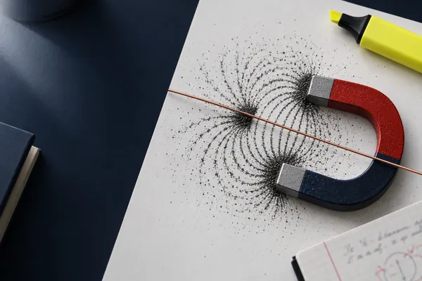
A magnetic field is a region where a magnet, a current-carrying wire or a moving charge feels a force. We draw it with field lines: the direction of the line shows the direction a free north pole would move, and closer lines mean a stronger field. Between two flat magnet poles the field is uniform, with parallel, equally spaced lines running from north to south.
A long straight wire has a field made of circles around the wire. Use the right-hand grip rule: point the thumb along the conventional current and your fingers curl in the direction of the field. The circles are closer together near the wire, where the field is strongest, and spread out further away.
A flat circular coil gives a field through the middle of the loop that looks like that of a short bar magnet. A solenoid is a long coil, and inside it the field is strong and almost uniform, with lines parallel to the axis. Outside it, the pattern is like a bar magnet's, with one end acting as a north pole and the other as a south pole. The field is strengthened by increasing the current, adding more turns per metre, or inserting a soft iron core.
When two fields overlap, they add as vectors. A wire in a uniform field produces a pattern in which the lines bunch on one side of the wire and thin out on the other, and the wire is pushed towards the weak side. This explains the direction of the force without any rule, though the left-hand rule is faster in the exam.
Fleming's left-hand rule and the direction of the force
Fleming's left-hand rule gives the direction of the force on a current-carrying conductor. Hold the thumb, first finger and second finger of your left hand at right angles to each other. The First finger points along the Field (north to south), the seCond finger points along the Conventional current (positive to negative), and the thuMb points in the direction of the force, which is the direction of Motion.
- Reverse the current and the force reverses.
- Reverse the field and the force reverses.
- Reverse both and the force stays the same.
- If the wire is parallel to the field, the force is zero.
The left-hand rule uses conventional current. For a beam of electrons the conventional current points opposite to the way the electrons move, so point your second finger against the electrons' velocity. Alternatively, treat the electrons as positive charges, find the direction of the force, and then reverse it.
F = BIL sin θ and the definition of the tesla
F = BIL sin θ
- F = force on the conductor / N
- B = magnetic flux density / T
- I = current / A
- L = length of conductor in the field / m
- θ = angle between the conductor (current) and the field
The force is greatest at θ = 90°, where it equals BIL, and zero at θ = 0° or 180°. Take care with the angle. It is the angle between the wire and the field lines, not between the wire and the force. If a question gives the angle between the wire and the plane of the poles, check which angle you need.
Rearranging for the field, B = F / (IL sin θ). When the wire is at right angles to the field, B = F / IL, and this is the idea behind the definition of the unit.
Magnetic flux density is also the flux per unit area: B = Φ/A when the field is perpendicular to the area. This is the link into electromagnetic induction, where the flux through a coil is what matters. Typical values are tiny for the Earth's field, small for fridge magnets and large for the strong magnets used in medical scanners.
Measuring B with a current balance
One way to measure the flux density between magnet poles uses a top-pan balance. Place a magnet with a yoke on the balance, so the field is uniform between two poles. Clamp a stiff wire of known length L so that it passes at right angles through the field without touching the magnet. Zero the balance, then pass a current I through the wire.
The magnet exerts a force on the wire, and by Newton's third law the wire exerts an equal and opposite force on the magnet. The balance reads a change in mass Δm, so the force is F = Δm × g. Then B = F / IL.
- Place the magnet assembly on the balance and zero it.
- Clamp the wire so that a known length L lies at right angles to the field.
- Increase the current in steps with a variable resistor, recording I from an ammeter.
- Record the balance reading Δm each time.
- Plot F = Δm × g against I. The gradient is BL, so B = gradient / L.
A graph is better than a single value because it averages out errors and shows whether F is proportional to I. The largest uncertainty is often the effective length of wire in the field, because the field is weaker at the edges of the poles. A Hall probe can measure B directly and is a good check, but you do not need Hall-effect theory for this method.
Force on a moving charge: F = BQv
A current is moving charge, so a field must also exert a force on each moving charge. Derive it from F = BIL. In time t, a charge Q passes a point, so I = Q/t. In that time, the charge moves a distance L = vt along the wire. Substitute: F = B(Q/t)(vt), so the t cancels.
F = BQv sin θ, and for v ⟂ B: F = BQv
- Q = charge on the particle / C
- v = speed / m s⁻¹
- θ = angle between the velocity and the field
For a charge moving parallel to the field, the force is zero.
The force on a moving charge is always at right angles to its velocity. Therefore the force does no work, and the speed of the particle stays the same. The field changes only the direction of travel. For a positive charge, use the left-hand rule with the second finger along the velocity. For a negative charge such as an electron, reverse the direction of the thumb.
Circular paths and the velocity selector
If a charged particle enters a uniform field at right angles to it, the force is perpendicular to its velocity and constant in size. That is the condition for uniform circular motion, with the magnetic force acting as the centripetal force:
BQv = mv²/r so r = mv / BQ
- m = mass of the particle / kg
- r = radius of the path / m
A faster particle moves in a larger circle. A stronger field gives a smaller one. The time for one circle is T = 2πm / BQ, which does not depend on speed.
The period is independent of speed, which is why fast particles go round bigger circles in the same time. See circular motion for the background to centripetal force.
A velocity selector uses crossed electric and magnetic fields to pick out particles of a chosen speed. The electric field exerts a force qE in one direction. The magnetic field is arranged to exert a force qvB in the opposite direction. Only a particle whose speed makes the two forces equal passes straight through undeflected. Set qE = qvB, and the charge cancels:
v = E / B
- E = electric field strength between the plates / V m⁻¹ (E = V/d)
- B = magnetic flux density / T
Note that the selected speed does not depend on the particle's charge or mass. After the selector, a beam of particles of one speed can be sent into a region with only a magnetic field, where the radius r = mv / BQ separates particles of different mass-to-charge ratio. That is how a simple mass spectrometer works. See coulombs law and electric fields for the electric part of the story.
Worked examples
Force on a wire at an angle
A straight wire of length 0.15 m carries a current of 4.0 A in a uniform field of flux density 0.25 T. The wire makes an angle of 60° with the field. Calculate the force on the wire and state its direction relative to the field and the wire.
- F = BIL sin θ = 0.25 × 4.0 × 0.15 × sin 60°.
- BIL = 0.150 N and sin 60° = 0.866.
- F = 0.150 × 0.866 = 0.130 N.
- The force is at right angles to both the wire and the field.
Answer F = 0.13 N, perpendicular to both the wire and the field
Measuring B with a balance
A conductor of length 0.060 m, perpendicular to a uniform field, carries a current of 3.0 A. The reading on the balance changes by 0.78 g. Calculate the magnetic flux density.
- Δm = 0.78 g = 0.78 × 10⁻³ kg.
- Force = Δm × g = 0.78 × 10⁻³ × 9.81 = 7.65 × 10⁻³ N.
- B = F / IL = 7.65 × 10⁻³ / (3.0 × 0.060) = 7.65 × 10⁻³ / 0.18.
- B = 0.0425 T.
Answer B = 0.043 T (2 s.f.)
Electron in a magnetic field
An electron moves at 2.0 × 10⁷ m s⁻¹ at right angles to a uniform magnetic field of 1.5 × 10⁻³ T. Calculate (a) the force on the electron, (b) the radius of its path and (c) the time for one revolution.
- (a) F = BQv = 1.5 × 10⁻³ × 1.60 × 10⁻¹⁹ × 2.0 × 10⁷ = 4.8 × 10⁻¹⁵ N.
- (b) r = mv / BQ = (9.11 × 10⁻³¹ × 2.0 × 10⁷) / (1.5 × 10⁻³ × 1.60 × 10⁻¹⁹) = 1.822 × 10⁻²³ / 2.4 × 10⁻²² = 0.0759 m.
- (c) T = 2πr / v = 2π × 0.0759 / 2.0 × 10⁷ = 2.38 × 10⁻⁸ s.
Answer (a) 4.8 × 10⁻¹⁵ N (b) 7.6 cm (c) 2.4 × 10⁻⁸ s
Velocity selector
The plates of a velocity selector are 0.020 m apart with a potential difference of 600 V. The magnetic flux density is 0.050 T. Calculate the speed of the particles that pass through undeflected.
- E = V/d = 600 / 0.020 = 3.0 × 10⁴ V m⁻¹.
- For no deflection qE = qvB, so v = E / B.
- v = 3.0 × 10⁴ / 0.050 = 6.0 × 10⁵ m s⁻¹.
Answer v = 6.0 × 10⁵ m s⁻¹, whatever the particle's charge or mass
Accelerated, then deflected
An electron is accelerated from rest through a potential difference of 1500 V, then enters a uniform field of 0.020 T at right angles to it. Calculate the radius of its path.
- Energy gained: eV = ½mv², so v = √(2eV/m).
- v = √(2 × 1.60 × 10⁻¹⁹ × 1500 / 9.11 × 10⁻³¹) = √(5.27 × 10¹⁴) = 2.30 × 10⁷ m s⁻¹.
- r = mv / BQ = (9.11 × 10⁻³¹ × 2.30 × 10⁷) / (0.020 × 1.60 × 10⁻¹⁹).
- r = 2.09 × 10⁻²³ / 3.2 × 10⁻²¹ = 6.5 × 10⁻³ m.
Answer r = 6.5 mm
Common mistakes
- Using the wrong angle. In F = BIL sin θ, θ is between the wire and the field, not between the wire and the force.
- Right hand instead of left. Use the left hand for force in a motor, and be consistent.
- Using electron movement for current. Fleming's rule uses conventional current, so reverse for electrons.
- Forgetting the charge is in coulombs. A proton or electron has charge 1.60 × 10⁻¹⁹ C, not 1.
- Saying the magnetic force speeds the particle up. The force is perpendicular to the velocity, so the speed stays the same.
- Mixing mass and weight on the balance. The balance reads kg or g. Multiply by g to get the force.
- Measuring only one point. Plot force against current to find B from the gradient.
- Saying the electric and magnetic forces in a selector are in the same direction. They must be opposite for a particle to go straight.
How OCR A examines this topic
Magnetic fields belong to the Electromagnetism topic in the Particles and medical physics module. Expect a mix of recall, calculation and explanation. Check the current specification for exactly which devices and methods are listed.
- Recall and definition: state the tesla, draw a field pattern for a wire or solenoid, apply the left-hand rule.
- Calculation: F = BIL sin θ, F = BQv and r = mv / BQ, often with an energy step first (eV = ½mv²).
- Practical: the balance method, how to improve accuracy, and graph analysis of F against I.
- Explanation: why the path is circular, why the speed is constant, why the velocity selector works at one speed only.
Synoptic links are strong. Circular motion provides the centripetal force condition, covered in circular motion. Electric fields supply the second force in the selector, linking to coulombs law and electric fields. Flux density feeds straight into electromagnetic induction, and charged-particle motion appears in the context of particle accelerators and the deflection of beta particles in radioactive decay and half-life.
Practice questions
A wire of length 0.30 m carries a current of 5.0 A in a uniform field of 0.80 T. Calculate the maximum force on the wire, and the force when the wire makes an angle of 30° with the field.3 marks
Show the answer
Answer: 1.2 N at 90°; 0.60 N at 30°
F(max) = BIL = 0.80 × 5.0 × 0.30 = 1.2 N. At 30°: F = 1.2 × sin 30° = 0.60 N.
A 0.080 m length of wire at right angles to a field carries 2.5 A and experiences a force of 0.12 N. Calculate the flux density.2 marks
Show the answer
Answer: 0.60 T
B = F / IL = 0.12 / (2.5 × 0.080) = 0.12 / 0.20 = 0.60 T.
A wire of length 0.25 m carries 5.0 A in a field of 0.40 T and experiences a force of 0.15 N. Calculate the angle between the wire and the field.3 marks
Show the answer
Answer: 17°
sin θ = F / BIL = 0.15 / (0.40 × 5.0 × 0.25) = 0.15 / 0.50 = 0.30. θ = sin⁻¹(0.30) = 17.5°, which is 17° to 2 s.f. (taking the smaller angle, as the other solution is 163°).
An electron moves at 3.0 × 10⁶ m s⁻¹ at right angles to a field of 0.040 T. Calculate the force on it and the radius of its path.4 marks
Show the answer
Answer: 1.9 × 10⁻¹⁴ N; 0.43 mm
F = BQv = 0.040 × 1.60 × 10⁻¹⁹ × 3.0 × 10⁶ = 1.92 × 10⁻¹⁴ N. r = mv / BQ = 9.11 × 10⁻³¹ × 3.0 × 10⁶ / (0.040 × 1.60 × 10⁻¹⁹) = 2.733 × 10⁻²⁴ / 6.4 × 10⁻²¹ = 4.3 × 10⁻⁴ m.
A velocity selector has an electric field of 2.4 × 10⁴ V m⁻¹ and a magnetic flux density of 0.080 T. Calculate the speed of the particles selected. Explain why the answer does not depend on the charge of the particle.4 marks
Show the answer
Answer: 3.0 × 10⁵ m s⁻¹
v = E / B = 2.4 × 10⁴ / 0.080 = 3.0 × 10⁵ m s⁻¹. For no deflection qE = qvB, and q appears on both sides, so it cancels.
Explain why a charged particle moving at right angles to a uniform magnetic field follows a circular path at constant speed.3 marks
Show the answer
Answer: The force is always perpendicular to the velocity, so it changes direction but does no work, and it acts as a centripetal force of constant size.
Force F = BQv is perpendicular to v. Perpendicular force does no work, so kinetic energy and speed are unchanged. Constant speed gives constant force magnitude, always towards a fixed centre, which is circular motion.
Next steps
Practise F = BIL sin θ and F = BQv until the rearrangements feel automatic. Then move to electromagnetic induction to see what happens when the flux through a coil changes, and revisit circular motion for the centripetal force link. Browse the full Particles and medical physics module, or practise this topic with step-by-step marking.
Frequently asked questions
What is the formula for force on a current carrying conductor?
F = BIL sin θ, where B is the flux density, I is the current, L is the length of wire in the field and θ is the angle between the wire and the field. At right angles it simplifies to F = BIL. If the wire is parallel to the field, the force is zero.
How do you use Fleming's left-hand rule?
Hold your left hand with thumb, first finger and second finger at right angles. Point the first finger along the field, north to south, and the second finger along the conventional current. Your thumb then points in the direction of the force.
What is the definition of the tesla?
One tesla is the flux density that gives a force of 1 N on a 1 m length of wire carrying 1 A when the wire is at right angles to the field. Its unit can be written N A⁻¹ m⁻¹.
Why does a charged particle move in a circle in a magnetic field?
The magnetic force acts at right angles to the velocity, so it changes the direction of travel but not the speed. A constant-size force towards a fixed centre acts as the centripetal force, so BQv = mv²/r gives r = mv / BQ.
How does a velocity selector work?
Electric and magnetic fields are arranged to push a charged particle in opposite directions. When qE = qvB the two forces cancel and the particle goes straight through. This happens only at v = E / B, whatever the charge and mass.
Do I need to know about Hall probes for OCR A?
A Hall probe is a common lab tool for measuring flux density directly, so it is useful to know what it does. Check the current specification for whether the Hall effect itself is examined. The balance method on this page is the one to learn well.
Related guides


Written for the OCR A Level Physics A (H556) specification. Questions are original and written in exam style; they are not taken from OCR papers. Spotted a mistake? Tell us.